TL;DR
A cable’s ampacity — the current it can carry continuously without exceeding its insulation temperature limit — is not a fixed property of the cable. It depends on how the cable sheds heat. A single cable in free air runs cool. The same cable bundled with others in a tray runs hotter, because the cables around it are also producing heat and blocking its escape routes.
To stay compliant, the designer must apply a grouping correction factor that reduces the cable’s rated ampacity for the conditions it is actually installed in. IEC 60364-5-52 provides the correction-factor tables. Skip the factor and the cable is under-sized — it runs hotter than its insulation is rated for, ages faster, and the problem typically surfaces years after handover.
| The mistake | The consequence |
|---|---|
| Sizing cables on free-air ampacity, then bundling them | Cables run above their temperature rating |
| Ignoring the grouping correction factor | Under-sized conductors, accelerated insulation ageing |
| Packing a tray full to save tray runs | The worst-case derating penalty, applied to every circuit |
| Eyeballing it instead of calculating | A figure nobody can defend at audit |
Why grouped cables run hot
Every current-carrying conductor dissipates heat — the I²R loss in the copper or aluminium. That heat has to leave the cable, or the conductor temperature climbs until it reaches a steady state. A cable’s ampacity rating is simply the current at which that steady state sits exactly at the insulation’s maximum permitted temperature.
A single cable lying in free air is the easy case. Heat radiates and convects away from the whole surface, in every direction, into air that stays close to ambient.
Now put that cable in the middle of a bundle. Two things change, and both work against it:
- Its neighbours are also heat sources. The cables packed around it are carrying current and producing their own I²R loss. The air between the cables is no longer at ambient — it is warmed by the whole group.
- Its escape routes are blocked. A cable buried in a bundle can only shed heat through the cables touching it, which are themselves hot. It has no clear surface facing open air.
The result is a higher conductor temperature for the same current. To bring the centre cable back within its insulation rating, you have to carry less current through it — every cable in the group, in fact. That reduction is the derating, and it is not optional physics. The cable does not know its datasheet ampacity; it only knows how hot it is getting.
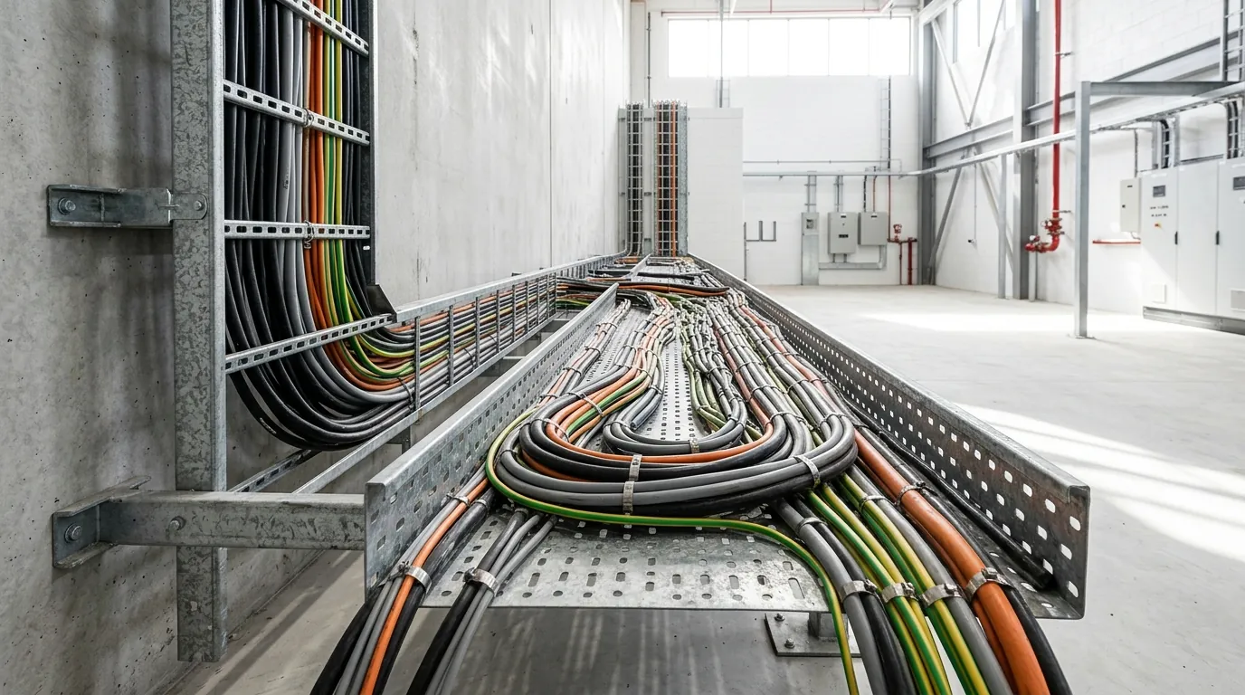
The penalty grows with the number of cables in the group and with how tightly they are packed. A loosely spaced pair on an open tray is barely affected. A dense block of feeders touching on all sides is the worst case.
The correction factor is not optional
This is the step that gets skipped, and it is the most consequential one.
A cable manufacturer’s datasheet quotes ampacity for a defined reference installation method — typically a single circuit, in free air or another standard arrangement, at a stated ambient temperature. That figure is a starting point, not the answer. The cable in your tray is almost never installed in the reference condition.
IEC 60364-5-52 — the international standard for the selection and erection of wiring systems — exists precisely to close this gap. It sets out current-carrying capacities for cables on tray and ladder, and it provides correction-factor tables that adjust the base ampacity for the conditions that actually apply, including:
- the number of grouped circuits or multi-core cables,
- the installation method — whether cables sit on a perforated tray, a solid tray, a ladder, or are enclosed,
- whether cables are touching or spaced, and arranged in single layer or stacked,
- the ambient temperature at the installation.
The designer’s job is to take the base ampacity, identify the correct reference method, apply the grouping correction factor for the real cable count and arrangement, and confirm the derated figure still covers the design current. The factors live in the standard’s tables — they vary by arrangement, and they must be read from the standard for the specific case, not assumed. In Indonesia, PUIL 2011, the national electrical installation code, governs the installation and is the document the work is inspected against.
The discipline is simple to state: never size a power cable on its free-air ampacity if it is going to be grouped. The correction factor is part of the sizing calculation, not an afterthought.
Tray geometry changes the picture
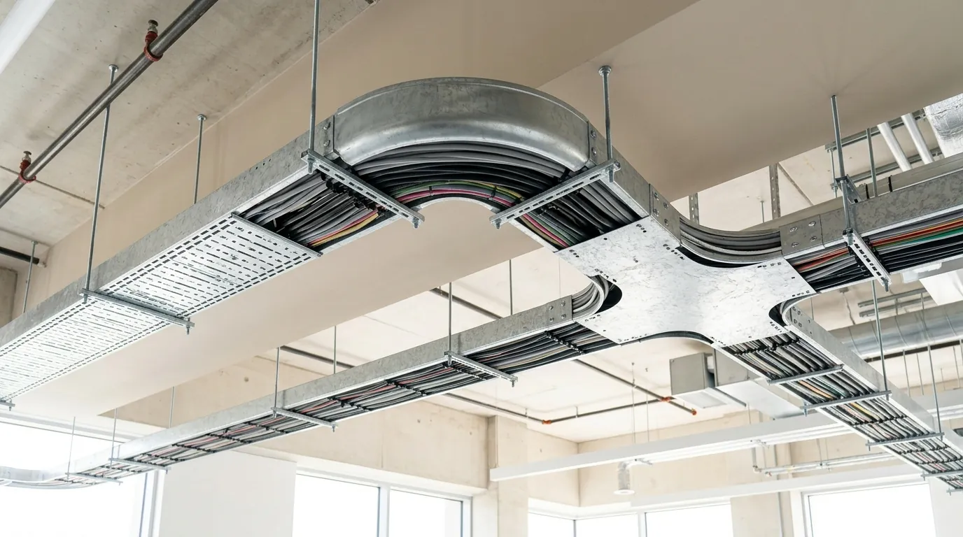
The derating penalty is not fixed by the cables alone. The support system carrying them changes how freely heat escapes — which is why the choice of cable management system is a thermal decision, not only a structural one.
Rank the three systems by how well they let air move around the cables:
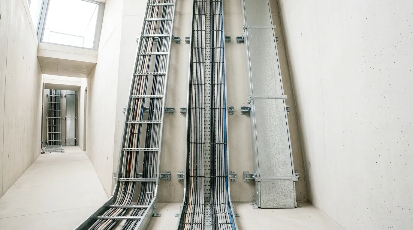
- An open-rung cable ladder is the most thermally open. The base is mostly empty space — rungs at 150 or 300 mm spacing — so air circulates freely around and beneath the cables. Metosu’s cable ladder is offered as SLW (perforated side rails) and SLU (non-perforated), both NEMA Class 8C.
- A perforated cable tray comes next. The perforations in the base (Metosu TRC) let air move through the tray floor, so heat is not trapped underneath the cables. A non-perforated tray (TRU) has a solid base — structurally similar, but with no airflow path through the bottom.
- Cable trunking (TKC/TKU) is a four-sided enclosure. It is the most thermally restrictive of the three: it traps heat around the grouped cables on every side. Trunking is the right choice for small or low-current circuits and for protection in exposed runs — but it is not the system for densely grouped power feeders that depend on airflow to stay within rating.
Two more arrangement choices matter as much as the system itself:
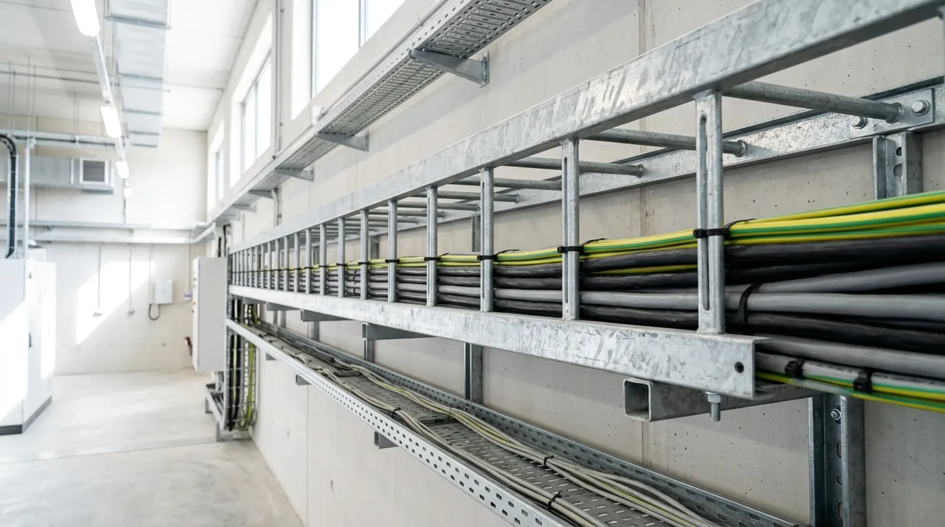
- Single layer beats stacked. Cables laid out in one layer each keep a face toward open air. Stack a second layer on top and the lower cables lose their upward escape route and gain a blanket of heat from above.
- Spacing beats bundling. Cables run with a gap between them — rather than touching — see a smaller grouping penalty, because each cable keeps clear air around it and the warmed air between cables can move away. The trade-off is tray width: spaced cables need a wider tray.
The same set of feeders, on the same building, can need a meaningfully different conductor size depending only on whether they are bundled tight on a solid tray or spaced out in a single layer on a ladder.
Practical rules
For the design engineer specifying the system:
- Do not pack a tray full. A tray loaded to its structural limit with bundled cables is also loaded to its worst-case thermal penalty. Leave the cables room to breathe.
- Prefer a perforated tray or a cable ladder for grouped power feeders. Reserve cable trunking for small or low-current circuits where the thermal restriction does not matter.
- Keep power cables to a single layer where you can. If layers are unavoidable, account for them in the derating — stacked cables carry a heavier penalty than the same cables side by side.
- Space cables instead of bundling them where tray width allows. The wider tray often costs less than the larger conductor it saves.
- Run the derating calculation — do not eyeball it. Apply the IEC 60364-5-52 correction factor for the actual cable count, arrangement, and installation method. A calculated figure is one you can defend; a guess is one you cannot.
How to specify it
Put the thermal intent into the documents, not just the cable schedule:
- State the installation method for each tray run — perforated tray, ladder, single layer or stacked — so the cable sizing and the as-built match.
- Reference IEC 60364-5-52 for the grouping correction factors, and PUIL 2011 as the governing installation code in Indonesia, so there is no ambiguity at inspection.
- Specify a tray fill that leaves the cables spaced and in a single layer where the design depends on it — and size the tray width to suit, rather than choosing the narrowest tray that physically fits the cables.
- Choose the cable management system to match the circuit: cable ladder or perforated tray for grouped power feeders, trunking for small protected circuits.
A cable schedule that has been derated correctly, on a tray specified with airflow in mind, is the version that still runs within temperature in year fifteen.
Talk to the Metosu technical team
If you are deciding between a perforated cable tray, a cable ladder, or cable trunking for a grouped-feeder run — and want the airflow and fill implications worked through before the tray width is locked — the Metosu engineering team can help.
Email marketing@metosu.com or contact Metosu.
Further reading
- Cable ladder vs cable tray — choosing between open-rung and perforated systems
- Cable tray sizing guide — fill, width, and load working through end to end
- Cable segregation: power, data and fire — separation rules alongside thermal grouping
- Cable tray support spacing — span and support, the structural half of the design
- Cable tray · Cable ladder · Full catalogue (PDF)