TL;DR
A steel cable tray or cable ladder is a conductor. The moment it is installed, it is part of the building’s earthing picture — whether the electrical design accounts for it or not. The only real question is whether that conductive path is continuous and bonded, or accidental and broken.
The weak point is almost never the tray section. It is the joint — splice plates, bolted connections, and galvanised or powder-coated contact faces that can interrupt the electrical path. A run is only as continuous as its worst joint.
| The assumption | The reality |
|---|---|
| ”The tray isn’t part of the earth system” | A metal run conducts; it is in the picture regardless |
| ”Bolted joints carry current fine” | A coated contact face can break continuity unless bonded |
| ”Continuity is the installer’s problem” | It is a design decision, then a verified site check |
| ”The tray can act as the CPC” | Only if calculated and specified — never by default |
A metal tray is always in the earthing picture
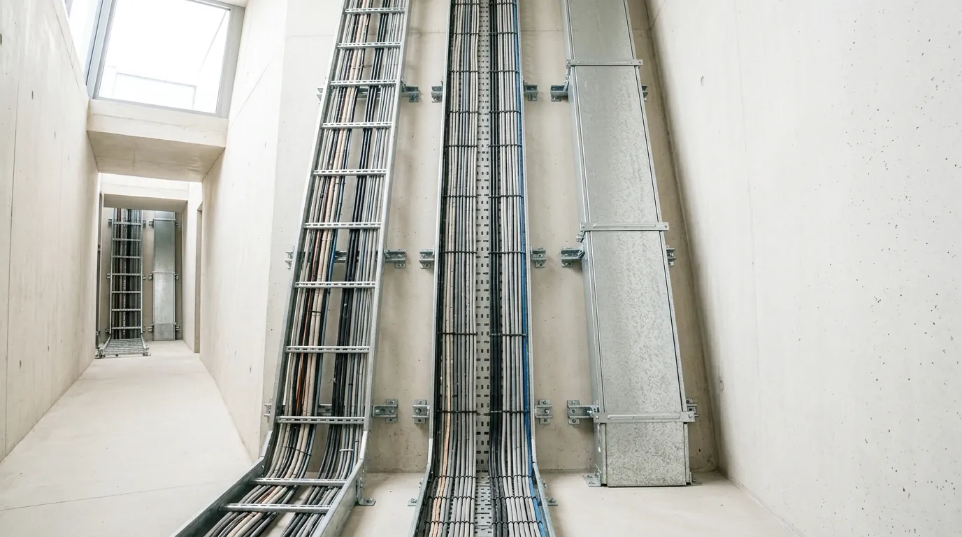
Cable tray and cable ladder are steel — Metosu manufactures them in steel from 1.0 mm (tray) up to 3.0 mm, hot-dip galvanised to ISO 1461 or Jotun powder coated. Steel conducts. That single fact is the starting point for this entire subject.
A metal tray run does not become part of the earthing system because a designer decides it should. It becomes part of it the moment it is bolted up and cables are laid in it. Under a fault — a damaged cable, a failed termination, a phase conductor touching the tray — the steelwork can become live. If the run is properly bonded back to the installation’s earthing system, that fault current has a defined, low-impedance path home, the protective device operates, and the circuit is cleared. If the run is not bonded, the steelwork can sit at a dangerous potential, waiting for someone to touch it.
So the choice is not whether the tray is in the earthing system. It is in. The choice is whether it is in deliberately and safely, or by accident and unsafely. That is what bonding decides.
The weak point is continuity across joints
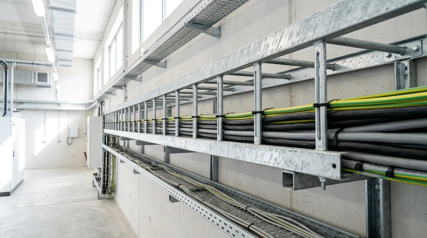
A single length of cable tray conducts end to end without difficulty. Problems start where two lengths meet.
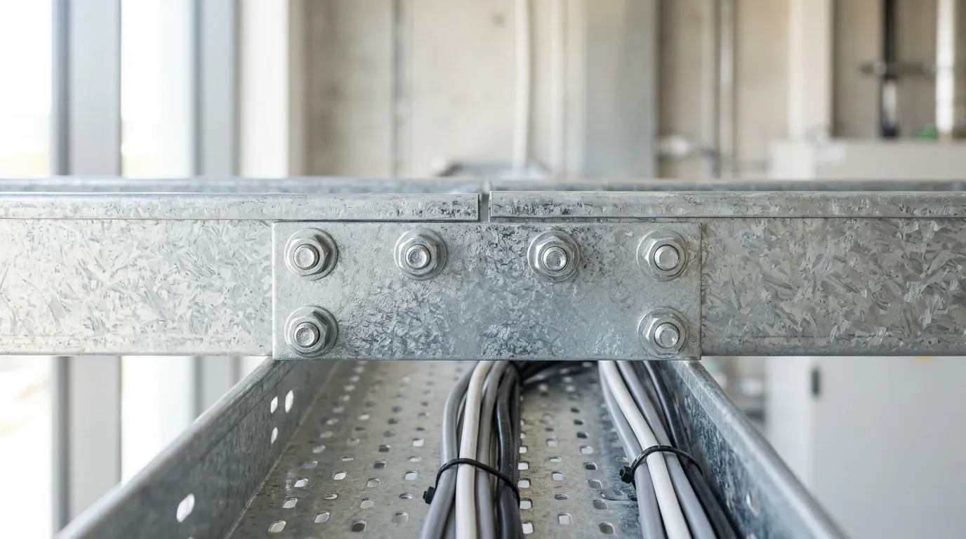
A typical run is assembled from sections joined by splice plates and bolts. Electrically, that joint is only as good as the metal-to-metal contact across it — and that contact is exactly where things go wrong:
- Coated contact faces. Hot-dip galvanising and powder coating are there to protect the steel from corrosion. They do their job well — and a powder-coated surface, in particular, is an insulator. Where two coated faces are simply bolted together, the coating can sit between them and interrupt the electrical path. The joint looks solid and mechanically is solid, while electrically it is compromised.
- Corrosion and loosening over time. Even a joint that is continuous on the day of installation can degrade. Vibration loosens bolts; moisture corrodes the contact area; thermal cycling works the connection. A joint relied on for earthing has to stay continuous for the life of the installation, not just at handover.
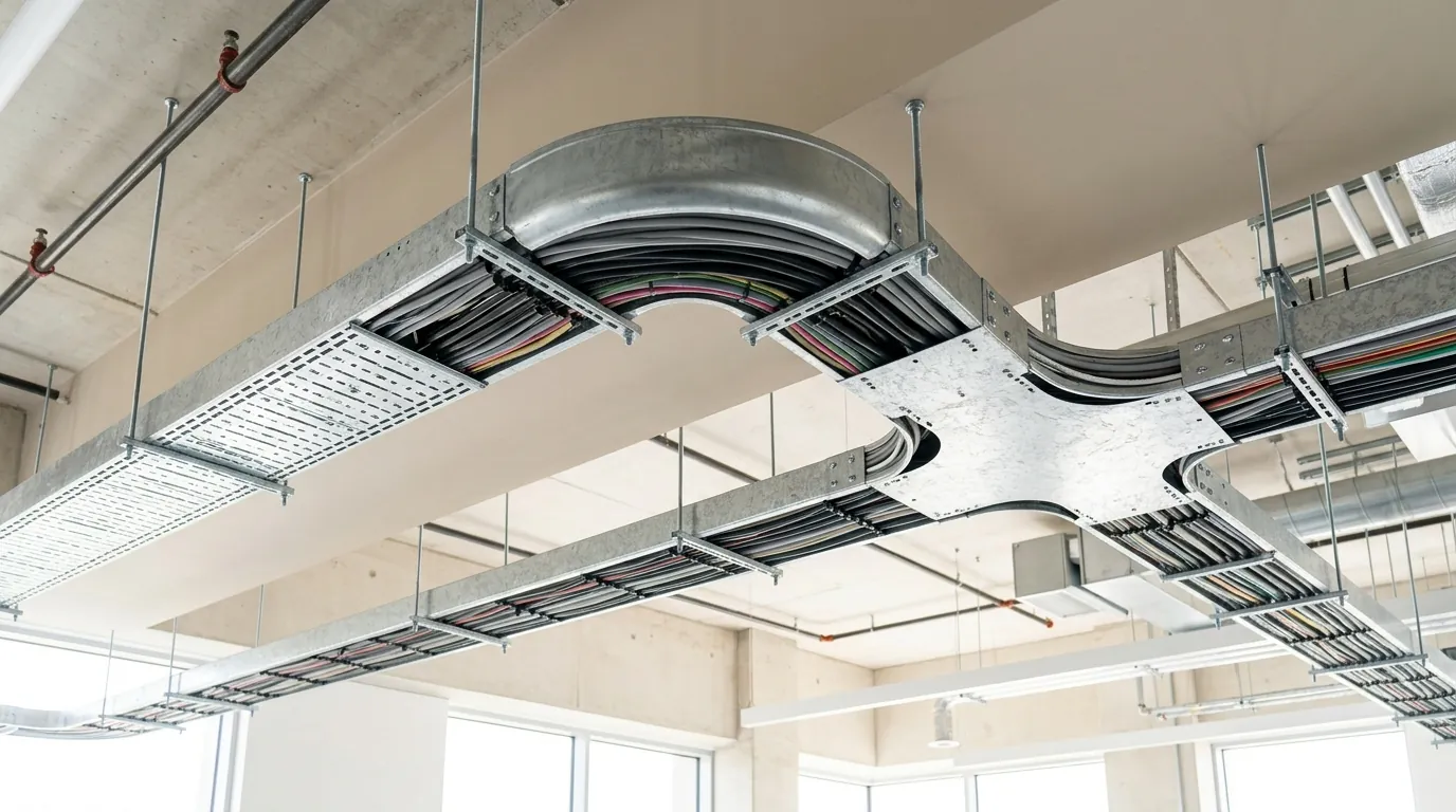
- Accessories and changes of direction. Bends, tees, reducers, and field-cut sections add joints — and every added joint is another place continuity can be lost.
The principle to carry through the whole design: a tray run is only as electrically continuous as its worst joint. One un-bonded coated connection in a 100-metre run breaks the earth path for everything beyond it. This is one of the most commonly overlooked items on Indonesian sites — the run is mechanically perfect and electrically discontinuous, and nobody checks until commissioning, if then.
What the standards require
The requirement to keep a metal support system electrically continuous is not a Metosu preference. It is written into the standards that govern these installations.
- IEC 61537 — the international standard for cable tray and cable ladder systems, adopted in Indonesia as SNI IEC 61537 — treats electrical continuity as a property of the system, not an afterthought. It includes an electrical-continuity requirement for cable tray and ladder systems: a system claiming compliance has to demonstrate that it can carry current across its joints, not just hold cables.
- PUIL 2011 — Persyaratan Umum Instalasi Listrik, the Indonesian electrical installation code — is the binding document for earthing and bonding in any installation in Indonesia. It governs how conductive parts are connected to the protective earthing system. A metal cable tray run is conductive metalwork that has to be brought into that earthing system, and PUIL 2011 is the code an inspector will hold the installation against.
- IEC 60364, and specifically IEC 60364-5-52 on the selection and erection of wiring systems, sits behind both. IEC 60364 covers protective conductors and the principles of protective earthing and bonding that PUIL implements in the Indonesian context.
The common thread across all three: a metal cable management system is expected to be electrically continuous and properly bonded. Cite the standards by name in your specification, and make continuity an explicit requirement — not an assumption.
Bonding jumpers: when and where to fit them
A bonding jumper — a short, rated conductor that bridges a joint — is the direct fix for the continuity problem. It carries current across a connection that the joint itself cannot be relied on to carry.
Fit a bonding jumper across a joint when:
- The contact faces are coated. This is the core case. Where powder-coated or galvanised faces are bolted together and the design relies on that joint for earthing, a jumper gives current a metal-to-metal path that does not depend on the coating being scraped through. If a joint is critical and coated, jumper it.
- The joint is in the earthing path of the run. Any joint that fault current is expected to cross — which, on a run used for earthing, is every joint — needs continuity you can trust.
- At expansion joints and movement gaps. Where a run is deliberately built to move, the connection across the gap cannot be relied on mechanically for current. Bridge it with a jumper.
- Across accessories and field modifications. Bends, tees, and any section cut or altered on site are joints — treat them the same way.
Where contact faces are clean bare steel and bolted tight, a joint may achieve continuity on its own. But the safe default for a coated system is to specify bonding jumpers at the joints the earthing path depends on, sized to the installation’s protective conductor requirements. A jumper is cheap. A discontinuous earth path discovered after handover is not.
Using a cable tray as a circuit protective conductor
A metal cable tray can serve as a circuit protective conductor (CPC) — the conductor that carries fault current back to earth for the circuits it supports. IEC 60364 recognises metal cable management systems as a category of protective conductor.
But this is a deliberate, calculated design decision — never an accidental default. Using a tray as a CPC is only valid when the designer has:
- Calculated that the tray’s cross-section and material give it adequate current-carrying capacity and fault withstand for the circuits concerned;
- Confirmed continuity across every joint along the path — which, for a coated system, means specifying bonding jumpers as above;
- Specified and documented the decision, so that everyone installing, inspecting, and later modifying the run knows the tray is doing protective-conductor duty.
The failure mode to avoid is the opposite: a run that was never designed as a CPC quietly being treated as one because it happens to be metal and happens to be there. If the tray is the CPC, it is the CPC by design, on paper, and verified. If it is not, the circuits need their own protective conductor and the tray is still bonded for safety. Either way, bonding the run is not optional.
Verifying continuity on site
A bonding design only counts if the installation actually delivers it. Continuity is one of the easiest things to specify and one of the easiest to lose between drawing and site.
Before sign-off:
- Check continuity across joints, not just end to end. A whole-run measurement can pass while a single mid-run joint is poor — the reading is dominated by the good joints. Continuity should be confirmed joint by joint along the runs that carry earthing duty.
- Inspect bonding jumpers are actually fitted where the design called for them, fitted to clean metal, and tightened.
- Include continuity in the commissioning record. A measured, documented continuity check across the run is the evidence an inspector — and PUIL 2011 — will expect, and it belongs in the project handover documentation.
- Re-check after later work. Any addition or modification adds joints. Continuity verified at handover is not continuity guaranteed forever.
Treat continuity verification as a defined step with a sign-off, not something assumed because the run looks complete.
Talk to the Metosu technical team
If you are specifying cable tray or cable ladder for an Indonesian installation and need to be confident the run will perform as part of the earthing system, Metosu can advise on jointing, accessories, and finish selection against IEC 61537, SNI IEC 61537, and PUIL 2011.
Email marketing@metosu.com or contact the Metosu technical team.
Further reading
- NEMA class vs tested capacity — how to verify a real load rating
- Cable tray and SNI standards in Indonesia — the standards framework explained
- Cable ladder vs cable tray — choosing the right system
- Cable tray support spacing — span, supports, and load
- Cable ladder · Cable tray · Full catalogue (PDF)